Making important decisions about the architecture and structure of a new project is crucial. It’s advisable to adopt a consistent approach, rather than allowing each screen or feature to be developed independently according to the developer’s whim. Today we are going to explore the theory about Clean Architecture, and in the next article we will explore how to implement Clean Architecture on an iOS app.
This consistency will prove valuable in the future, whether you return to the project after some time away or begin working on a part of the project that was developed by a team member. Having a clear understanding of the project’s structure and where to find everything will make your work more efficient.
Structure
When it comes to choosing an architecture for a new project, it’s important to prioritize modularity, scalability, maintainability, and testability. In this post, we’ll discuss the structure that I prefer to follow in my projects. Before diving into code examples, let’s define some key concepts.
- Vertical slicing involves splitting a project into different features. For instance, if our project displays a list of products and a shopping cart, we would have two separate features: “List Product” and “Shopping Cart”. Each feature contains everything required to function independently.
- Horizontal slicing is another popular way to structure an application. It involves dividing the project into layers such as the data layer, which manages data storage and retrieval; the presentation layer, which deals with the user interface and data formatting; and the domain layer, which contains the business logic. Following this approach, we can organize our project into one module for each layer.
Alternatively, we can combine both approaches. We can first divide our project into different features and then divide each feature by layers. This hybrid approach allows us to quickly locate the feature we need, and within it, we can easily identify the different layers that make up the feature.
App Architecture
An app architecture outlines the various components of an app and how they interact with each other. There are several popular design patterns, such as MVC, MVVM, and MVP, which are commonly referred to as architectures. However, these patterns only address the communication between the UI and a controller, view model, or presenter. An app architecture should also specify how we organize and communicate with other dependencies, such as networking, databases, and other frameworks. Additionally, any of these patterns can be used in conjunction with the Clean Architecture.
Clean Architecture
The Clean Architecture, proposed by Robert C. Martin, outlines how we can structure our application into different layers. Also, how these layers should communicate, and how they should depend on each other.
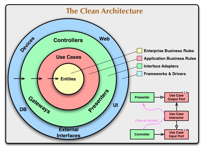
The Clean Architecture proposes four different layers: Entities, Use Cases, Interface Adapters, and Frameworks and Drivers. For more information, you can visit The Clean Code Blog. However, we will simplify a few of the concepts here.
Layers
We will be using a three-layered architecture consisting of:
- Domain: Models, use cases and interfaces.
- Data: Repositories and data sources.
- Presentation: ViewModel/Presenter/Controller and UI
It is important to understand how they interact with each other. The outer layer is the most low-level, meaning it is closer to implementation details such as the database or UI. The domain layer, on the other hand, is the most high-level, representing abstract concepts like models and business rules.
The dependency rule states that high-level layers should not depend on low-level layers. For example, models in the Domain layer should not have any direct dependency on the UI. If they need to communicate, such as when a use case requires information from a repository, we will use dependency inversion to avoid creating a dependency. This means that communication will be through an interface, rather than a direct reference to the concrete implementation.
Furthermore, the layers will only communicate with the most immediate layer. For example, the Presentation layer will not communicate directly with the Data layer. All communication will go through the use cases. This ensures that the system remains modular, with each layer encapsulating its own functionality and responsibilities.
Communication between layers
Let’s take a closer look at an example to understand how the components work together. Suppose we need to implement a feature that displays a list of players. When the user opens the screen, the application will fetch the list of players from an endpoint and display the results in the UI.
We have five components in our architecture: View, Presenter, Use Case, Repository, and Data Source. As we can see in the diagram, all components communicate with each other through an interface. This ensures that there is no direct coupling between components, and that each component can be modified or replaced without affecting the others.
One of the most important cases is the communication between the domain components and the data or presentation layer. For example, the Use Case may need access to a Repository to retrieve data, but it should not depend on the implementation of the Repository, only on its interface. This is the Dependency Inversion Principle in action, which ensures that high-level components in the domain layer are not directly dependent on low-level components in the data or presentation layer.
Note that the Repository interface is part of the Domain layer, which helps to avoid creating a dependency on the implementation of the Repository. This allows the implementation of the Repository to be modified or replaced without affecting the Domain layer.
Now let’s take a closer look at each component in the architecture.
Presentation
The View component is responsible for rendering the UI and communicating user events to the Presenter. In our architecture, the View receives updates in the form of a ViewModel, which is a plain data object that only contains the information needed to be displayed on the UI. For our example case, the View will communicate with the Presenter when the view appears, and will render the list of players on the UI when it receives a ViewModel.
The Presenter component’s main function is to receive View events, call Use Cases, and map the domain models returned from the Use Cases into View Models for the View to use. In our example, the Presenter will receive an event when the View appears, call the Use Case, receive the domain entity, and map the domain entity into a View Model that contains only the necessary information in a format convenient for the View.
The method used to update the View with the new ViewModel depends on the design pattern used in the architecture. In our case, the ViewModel will be an observable object, and the View will listen for changes on this model.
Data
Data Source: The responsibility of this class is to load data from various sources, such as an API call, a database, or in-memory storage. Depending on the use case, the implementation will vary. In our specific case, we will be loading player data from an API endpoint. Therefore, this class will make a network request using a network client, decode the response into a model, and return it. It’s worth noting that this model is not the domain entity, but rather a DTO (Data Transfer Object) that contains the decoding logic and is in the most appropriate format for decoding purposes.
Repository: The repository implementation will implement the repository interface. It will call the data source, receive a DTO, and then map this DTO into the domain model that the use case will receive. While it may seem like a waste of time to have two different models for the data source and domain, there are numerous benefits to this approach. By separating the two models, each can be in the best format for its respective use case. This separation also prevents the data source logic from influencing the domain model and reduces the likelihood of changes to the domain model due to changes in the data source model.
Domain
Entity: The purpose of the entity is to contain platform-independent business logic. This can take the form of plain classes or models, as well as domain logic or policies that define our business. In our case, the entity will be a simple struct containing a list of players. As an example of a policy, consider a scenario in which we cache this information for a few days. We could declare a policy to determine whether or not the cache is valid.
Use Case: The use case is responsible for performing any application-specific logic. It can be thought of as a set of commands necessary for our application to function. In our case, the use case will be to “load the list of players.”
Conclusion
Now that we have a brief summary of each component, let’s delve into the code to see concrete examples in the second part of this clean architectures series. Any feedback is appreciated, see you then!